
Keys & electronicsToyota Aqua NHP10
Aqua NHP10 Fuse Boxes: JDM Locations, Circuits & the Box Not to Open
Find the Aqua NHP10 engine-room and passenger-footwell fuses from Toyota's Japanese manuals: CIG, OBD, wiper and hybrid-fan circuits, the high-voltage box warning and the jump-start terminal.
- Time
- 10 minutes to identify the box and circuit
- Difficulty
- Easy
- Tools
- 2 needed
- Instructions
- 5 steps
Applies to Toyota Aqua NHP10 · Japan NHP10; Toyota February 2013 manual printed pp.309–315 and November 2015 manual printed pp.307–309, 395–397. Japan NHP10; Toyota February 2013 manual printed pp.309–315 and November 2015 manual printed pp.307–309, 395–397. Always compare the described parts, labels and specifications with your own vehicle and manual.
For owners in Sri Lanka / New Zealand / Kenya These are the cited Japan-market references, not local-market specifications or evidence of parts availability.
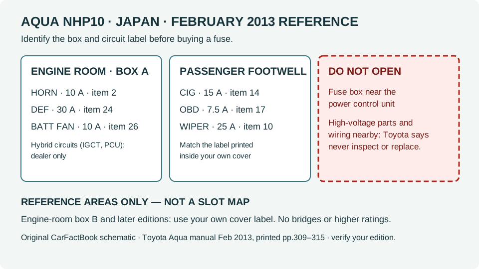
Identify before you buy
Pick the right box first, then the circuit
| What you have | What the evidence establishes | Next owner decision |
|---|---|---|
| Passenger footwell: CIG | 15 A; accessory socket, February 2013 table item 14 | Check the socket circuit against your cover label. |
| Passenger footwell: OBD | 7.5 A; diagnosis connector, item 17 | Relevant if a scan tool cannot power up; confirm the label. |
| Passenger footwell: WIPER | 25 A; wiper and washer, item 10 | Separate WASHER (15 A) and WIPER RR (15 A) entries exist. |
| Engine-room box A: BATT FAN | 10 A; traction-battery cooling fan, item 26 | Hybrid-related: report symptoms to a dealer rather than probing. |
| Fuse box near the power control unit | Toyota: never inspect or replace (high voltage) | Do not open; seek qualified hybrid service. |
Selection aid only. An unknown or conflicting configuration needs confirmation before purchase.
Have these references ready
- Toyota manual edition matching the car
- Failed-function notes and fuse-box cover label
Step-by-step instructions
Choose the correct manufacturer-backed specification
Use these source-backed checks to identify the option for your exact equipment. This is a selection guide, not a hands-on replacement procedure. If a component or label looks different on your car, stop and check your own manual.
- Step 1 of 5
Match the manual edition before trusting a circuit list
Toyota's February 2013 Japanese manual prints a full circuit table for engine-room fuse box A and the passenger footwell box. The November 2015 edition still shows engine-room box A, engine-room box B and the passenger footwell, but no circuit table. Use the cited table only alongside the printed label inside your actual cover; later production, dealer-fitted accessories or a different market edition can differ.
All steps ↑ - Step 2 of 5
Leave the fuse box near the power control unit alone
Both editions warn that the fuse box near the power control unit sits beside high-voltage parts and wiring, and that it must never be inspected or replaced by the owner: mishandling can cause electric shock, serious injury or death. If you cannot positively identify a box from the manual illustration, do not open it. Orange cables and anything inside the hybrid enclosure are outside this guide.
All steps ↑ - Step 3 of 5
Start from the failed function, not a fuse colour
Write down exactly what stopped working. In the February 2013 footwell table CIG is the 15 A accessory socket (item 14), OBD is the 7.5 A diagnosis connector (item 17) and WIPER is 25 A (item 10). In engine-room box A, HORN is 10 A (item 2), DEF is the 30 A rear defogger (item 24) and BATT FAN is the 10 A traction-battery cooling fan (item 26). Hybrid-system circuits such as IGCT and PCU are dealer matters.
All steps ↑ - Step 4 of 5
Use only the rated replacement and stop if it blows again
Toyota's procedure starts with the power switch OFF (or the key at LOCK on cars without smart entry), and requires the specified rating, a genuine Toyota or equivalent fuse and no modification of the fuse or box. If a replacement blows again, or the cause was an electrical overload, Toyota directs an inspection. Never fit a higher rating, foil or wire; a repeated failure is a fault to diagnose, not a fuse to keep buying.
All steps ↑ - Step 5 of 5
Know where the 12V jump-start terminal is, and use Toyota's sequence
The November 2015 manual places the jump-start terminal (救援用端子) under a cover inside the engine-room fuse box and gives a specific cable order, a charging period and a READY-light check, and states the Aqua cannot be push-started. Follow that printed procedure in full rather than a generic petrol-car method, and have the 12V system checked afterwards as Toyota advises. This page does not reproduce the step sequence.
All steps ↑
References & limitations
Where these instructions come from
Japan NHP10; Toyota February 2013 manual printed pp.309–315 and November 2015 manual printed pp.307–309, 395–397
Manufacturer facts are limited to the cited edition and configuration. The decision table and service-request checklist are original CarFactBook editorial aids, not a fault diagnosis, workshop procedure or approval of an unverified part.
Toyota Aqua February 2013 JDM manual ↗Manual section: Printed pp.309–315: box locations, engine-room box A items 1–31, passenger footwell items 1–23, high-voltage box warning
Instructions checked against manufacturer documentation; not a physical inspection of every vehicle.
- Toyota Aqua February 2013 JDM manual ↗ — Printed pp.309–315: box locations, engine-room box A items 1–31, passenger footwell items 1–23, high-voltage box warning
- Toyota Aqua November 2015 JDM manual ↗ — Printed pp.307–309: three box locations and high-voltage warning; pp.395–397: 12V jump-start terminal procedure